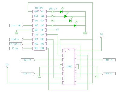
モータドライバ部分の回路図です。簡単。

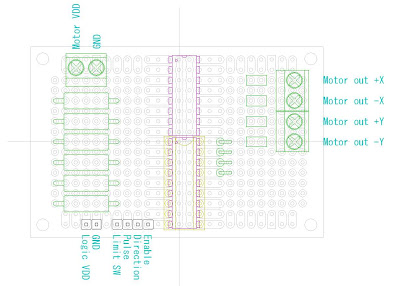
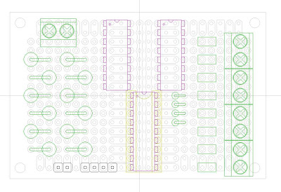
基板へのレイアウトはこんな感じで。基板はサンハヤトの ICB-87 を使います。
X,Z軸はモータがひとつですのでこれで。
電流制限抵抗は変更の可能性があるので回路図には入れていません。レイアウト上では6本まで乗せられるように場所を確保。110Ω2W品をパラレルで使って調整をしていくつもりです。
Y軸はモータが二つありますので、ドライバも2つ乗せ、完全並列で駆動します。
ポートのレイアウトを変更したので、モータドライバ部分のソフトを再掲載。
リミットスイッチの検出も追加しています。まだリミットスイッチは何も試してないけど。
// BiPolar Stepping Motor Driver for 16F1827
// compiler: MPLAB XC8 Compiler
// 2012/10
// Configration
// RA0,1,6,7: LED indicator or second input
// RA2: enable output to driver
// RA3,4: optional port
// RA5: Limit switch input
// RB0: optional port
// RB1: Enable input from controler
// RB2: Direction
// RB3: Pulse input
// RB4,5,6,7: motor OUTPUT
// Driving method: 1-2 phase
#include <pic.h>
__CONFIG(CLKOUTEN_OFF & FOSC_INTOSC & FCMEN_OFF & IESO_OFF & BOREN_ON &
PWRTE_ON & WDTE_OFF & MCLRE_OFF & CP_OFF & CPD_OFF) ;
__CONFIG(PLLEN_ON & STVREN_ON & WRT_OFF & BORV_HI & LVP_OFF);
short PulseLevel=1; // memory rotation pulse level in last loop: active low
int StepNumber=0; // increment or decrement by every rotation pulse
// according to the direction
interrupt LimitSwitch()
{
}
void main()
{
OSCCON=0b01110010; // internal clock 8MHz
OPTION_REG=0b00000000; //intl.pullup enable, INT edge fall
ANSELA=0b00000000; // No analog for PORTA
ANSELB=0b00000000; // No analog for PORTB
TRISA=0b00100000; // Set I/O according to configuration
TRISB=0b00001111; // Set I/O according to configuration
PORTA=0b00000000; // reset out put
PORTB=0b00000000; // reset out put
WPUB=0b00001111; //intl.pullup RB0,1,2,3
while(1)
{
if((RB1==0) && (RA5==1)) // check enable/disable and Limit Switch status
{
RA2=1; // put enable signal to motor driver
if((RB3==0) && (PulseLevel==1))
{
PulseLevel=0;
if(RB2==0) //check direction CW/CCW
StepNumber++;
else
StepNumber–;
switch(StepNumber%8)
{
case 0:
PORTB = (0b10010000);
PORTA = (0b01000010);
break;
case 1:
PORTB = (0b10000000);
PORTA = (0b00000010);
break;
case 2:
PORTB = (0b10100000);
PORTA = (0b10000010);
break;
case 3:
PORTB = (0b00100000);
PORTA = (0b10000000);
break;
case 4:
PORTB = (0b01100000);
PORTA = (0b10000001);
break;
case 5:
PORTB = (0b01000000);
PORTA = (0b00000001);
break;
case 6:
PORTB = (0b01010000);
PORTA = (0b01000001);
break;
case 7:
PORTB = (0b00010000);
PORTA = (0b01000000);
break;
}
}
else if((RB3==1) && (PulseLevel==0))
PulseLevel=1;
}
else if(RB1==1) // check & put enable/disable
{
PORTB = (0b00000000);
PORTA = (0b00000000);
RA2=0;
}
else if(RA5==0) // Limit Switch detected
{
RA2=0;
PORTB = (0b00000000);
PORTA = (0b11000011); // All LED on
}
}
}
では実装開始。