RAMPS基板にファームウェアを乗せます。RAMPSというのはコントローラ基板、つまりハードウェアの名称です。これにファームウェアを組み合わせて3Dプリンタの制御基板を作っていくわけです。
今回使うRAMPSのバージョンは1.4です。この基板に合わせて設計されているファームはSprinterとMarlinがあります。ネットをざっと見てみるとMarlinがメジャーなようですので私もMarlinを使うことにしました。
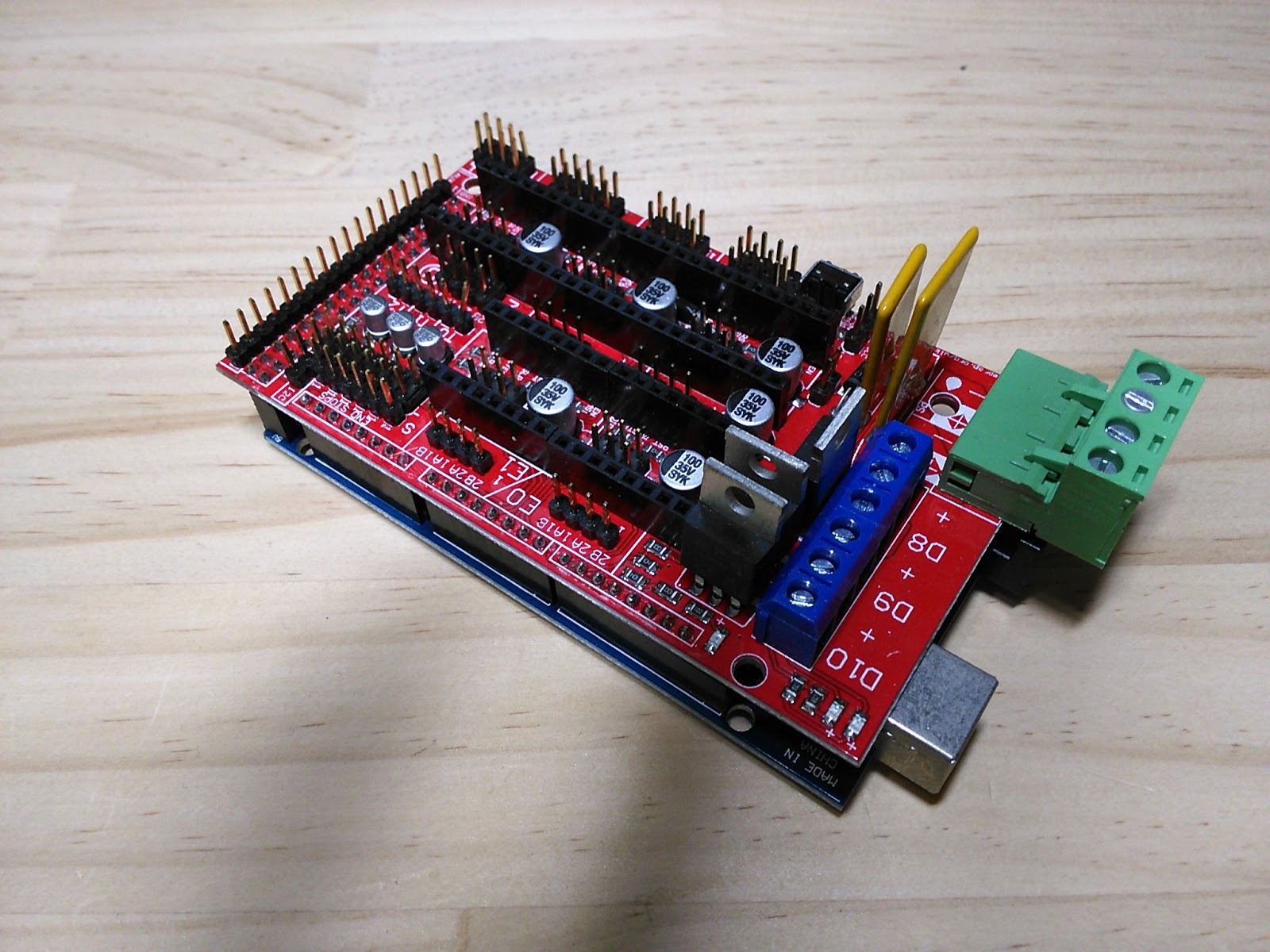
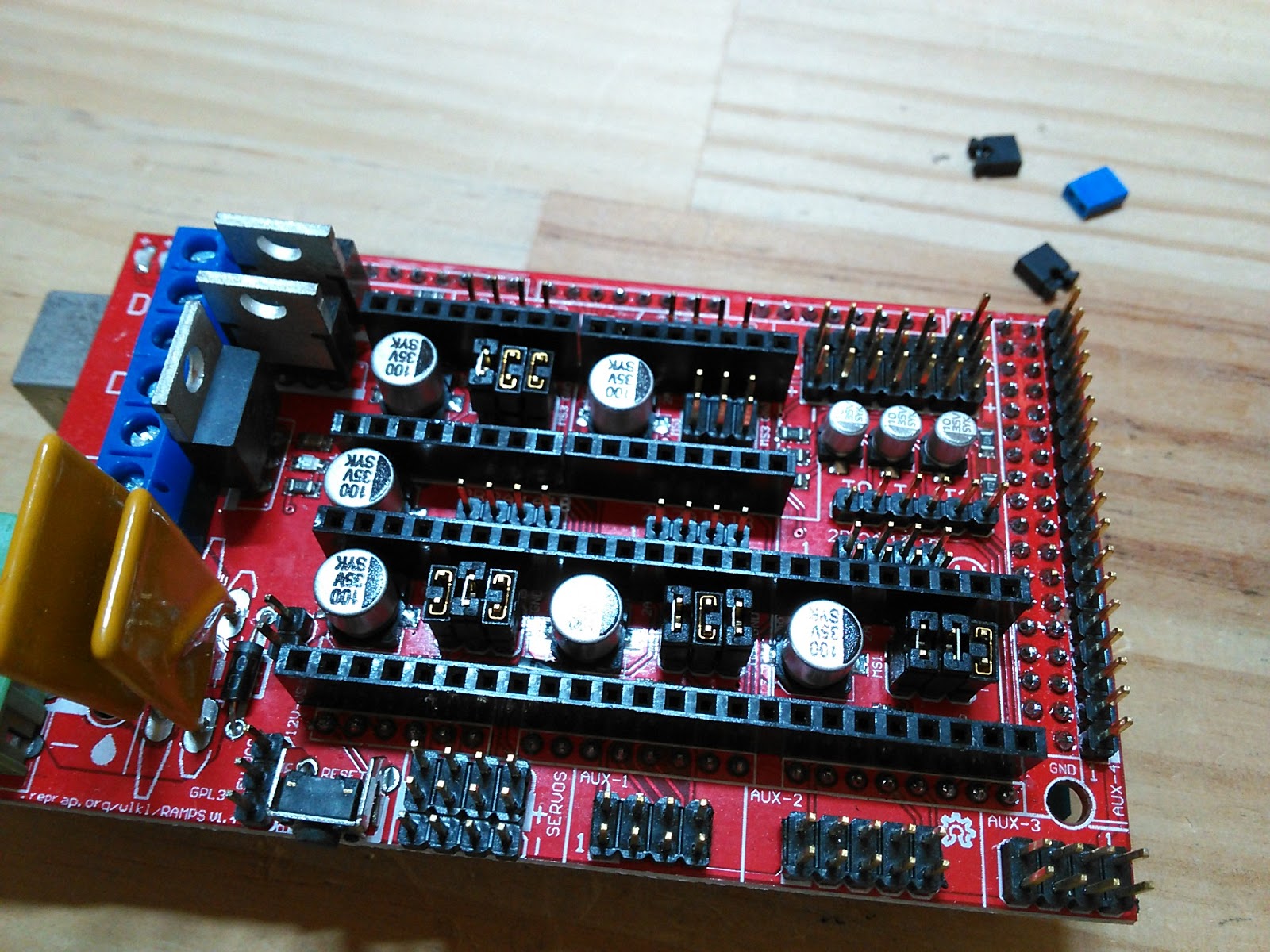
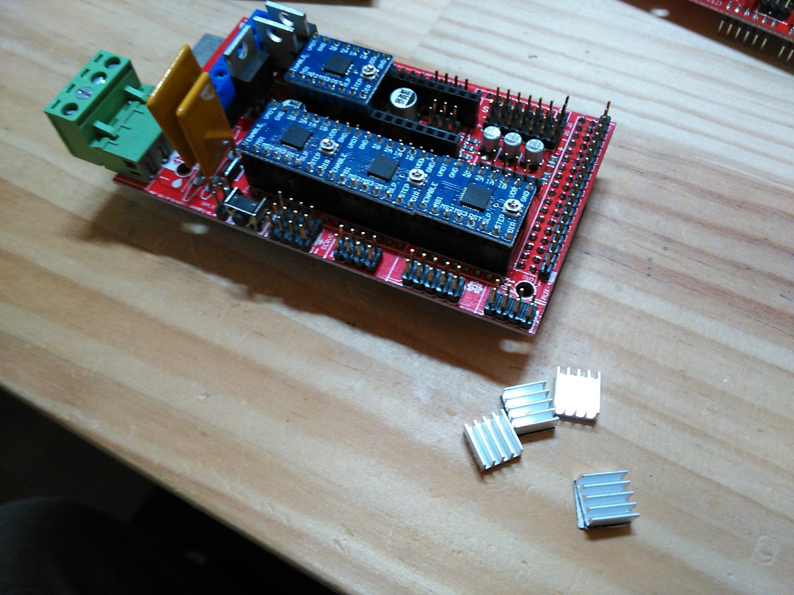
ボードの下準備をします。といってもモータドライバ乗っけておくだけですが。

モータドライバはたくさん余っているPololuのA4988互換ボードを使います。RAMPS基板ももちろんサポートしています。
モータドライバにはマイクロステップの設定があります。下の写真のピンソケットの間に見えるピンヘッダ(ぜんぶそうっちゃそうですが:笑)です。
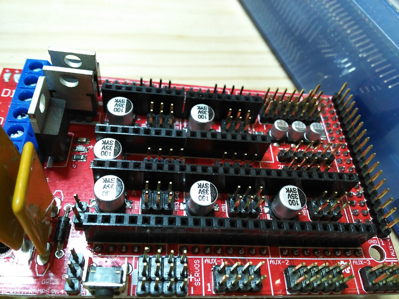
ここにジャンパを付けます。静かなのが良いので1/16ステップで行こうと思います。
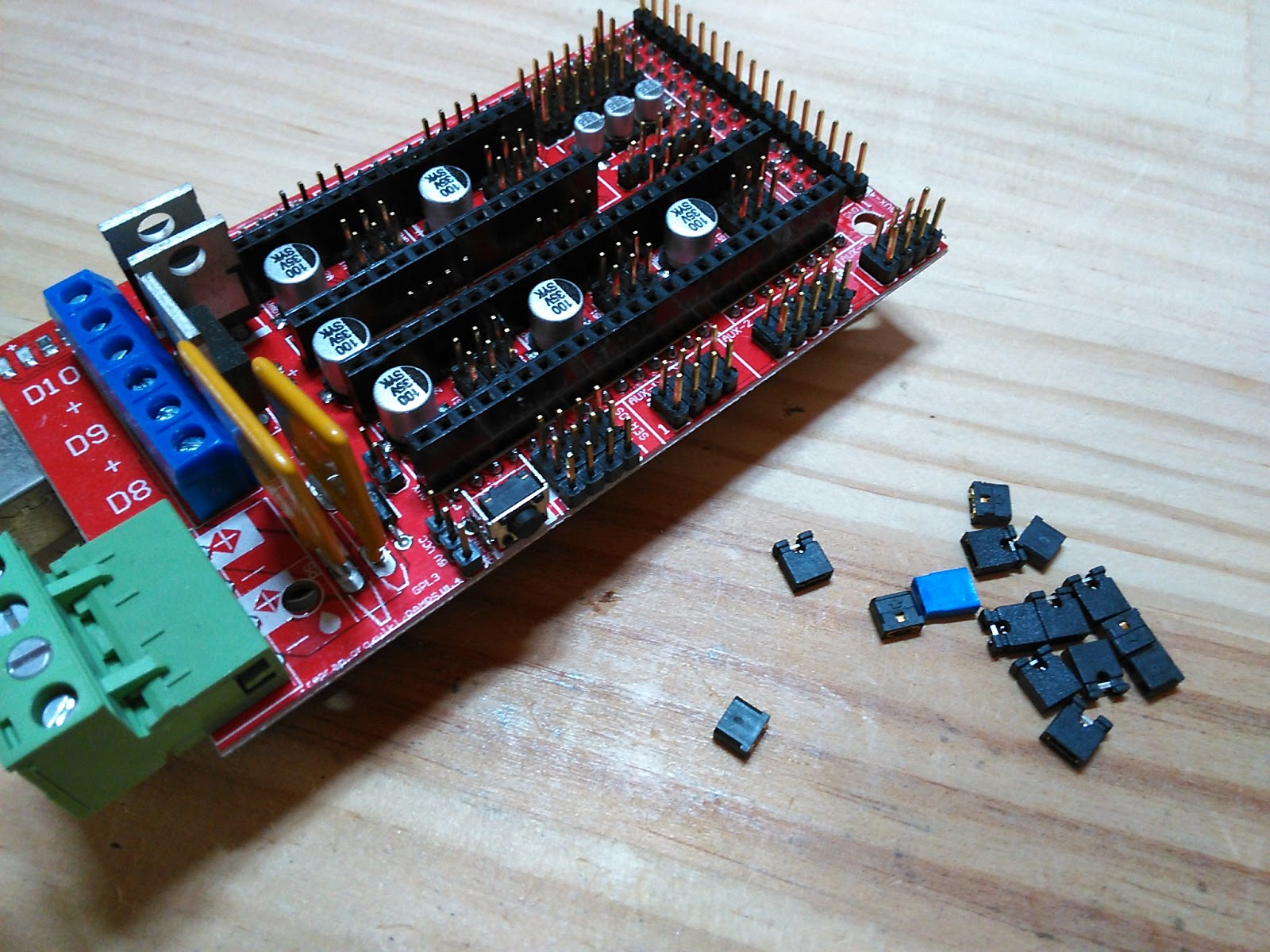
1/16はジャンパを3つとも短絡します。確か。こんな感じに。
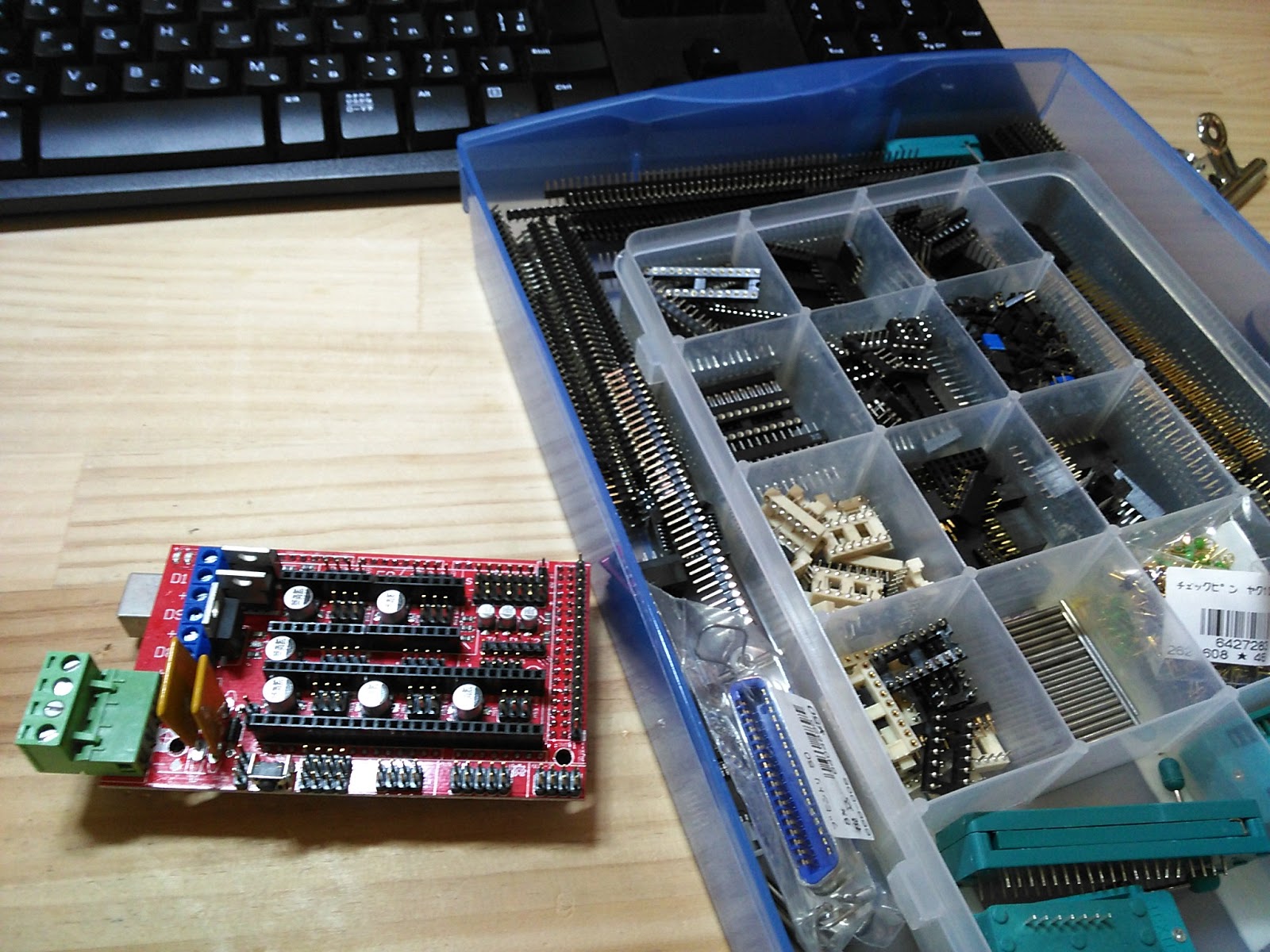
ドライバ基板はあっちこっちで遊んだものがありますので、それを取り外してリサイクルします。電流設定とかあるのですが、それは回り始めてから考えます。
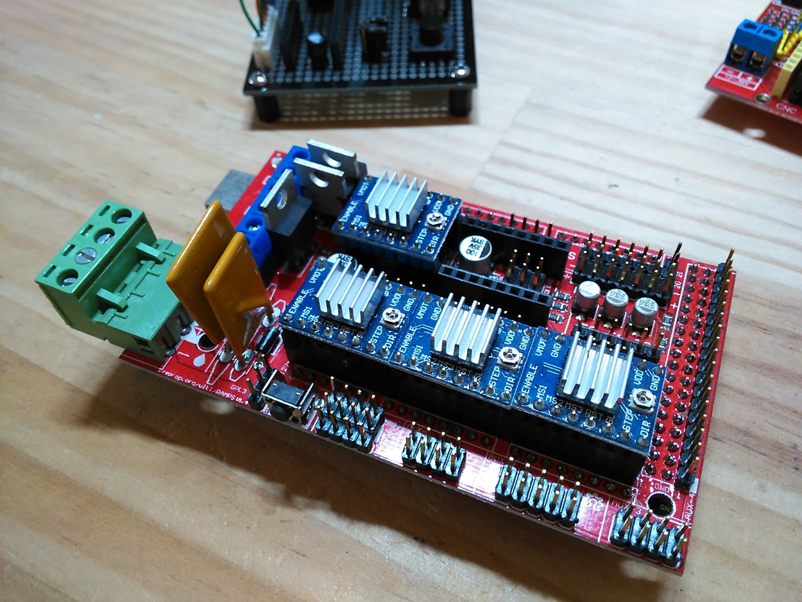
載せました。一か所余っていますが、これはエクストルーダ2用、つまり二つめのエクストルーダ用モータの駆動のためのものですので現構成では不要です。
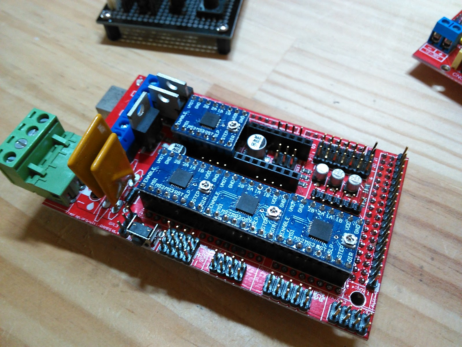
念のために放熱版も乗っけとくかな。
ちょうどいい奴がありました。しかも伝熱両面もついています。aitendoで買ったようなかすかな記憶が(笑
載せるだけ。
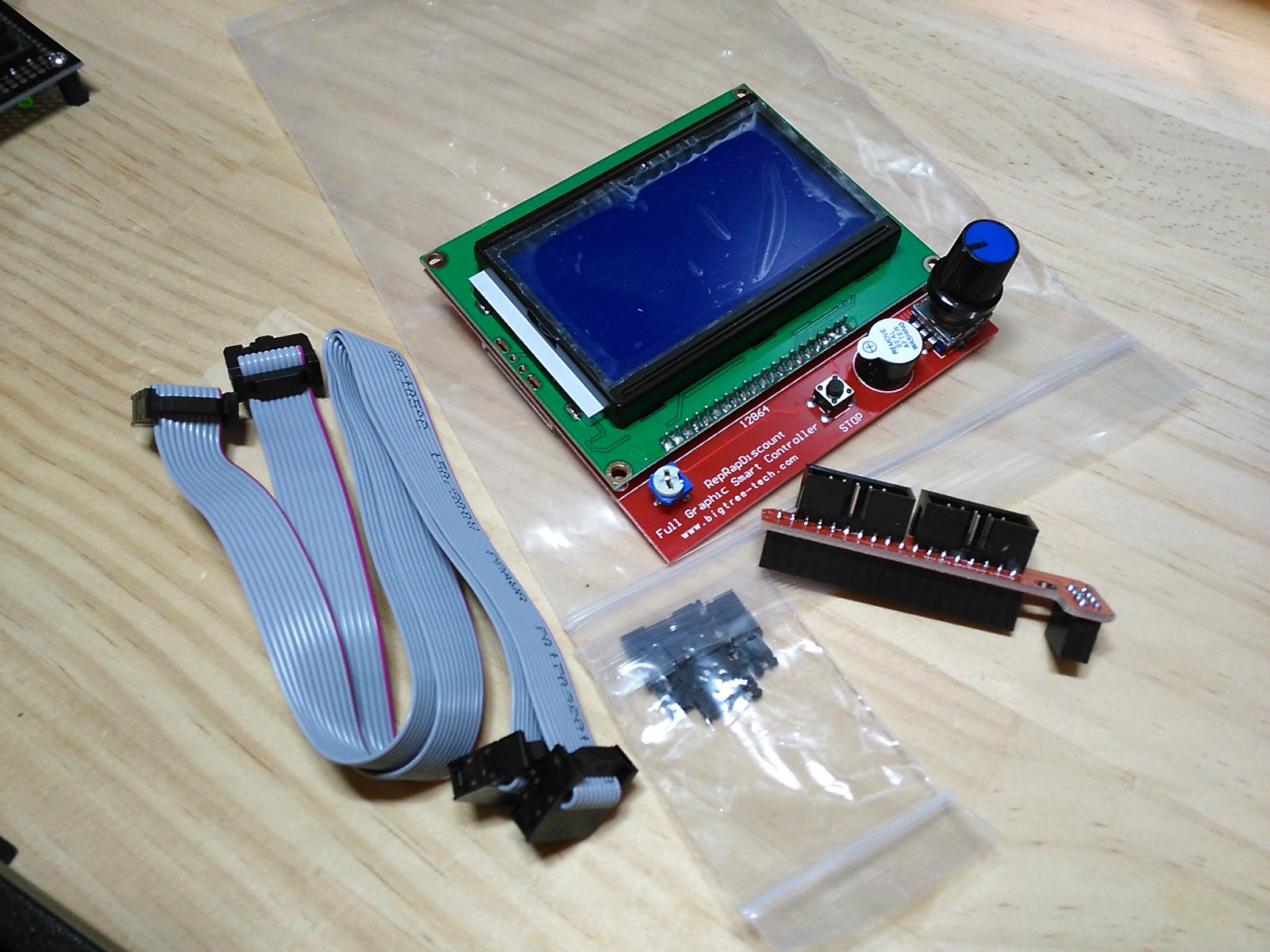
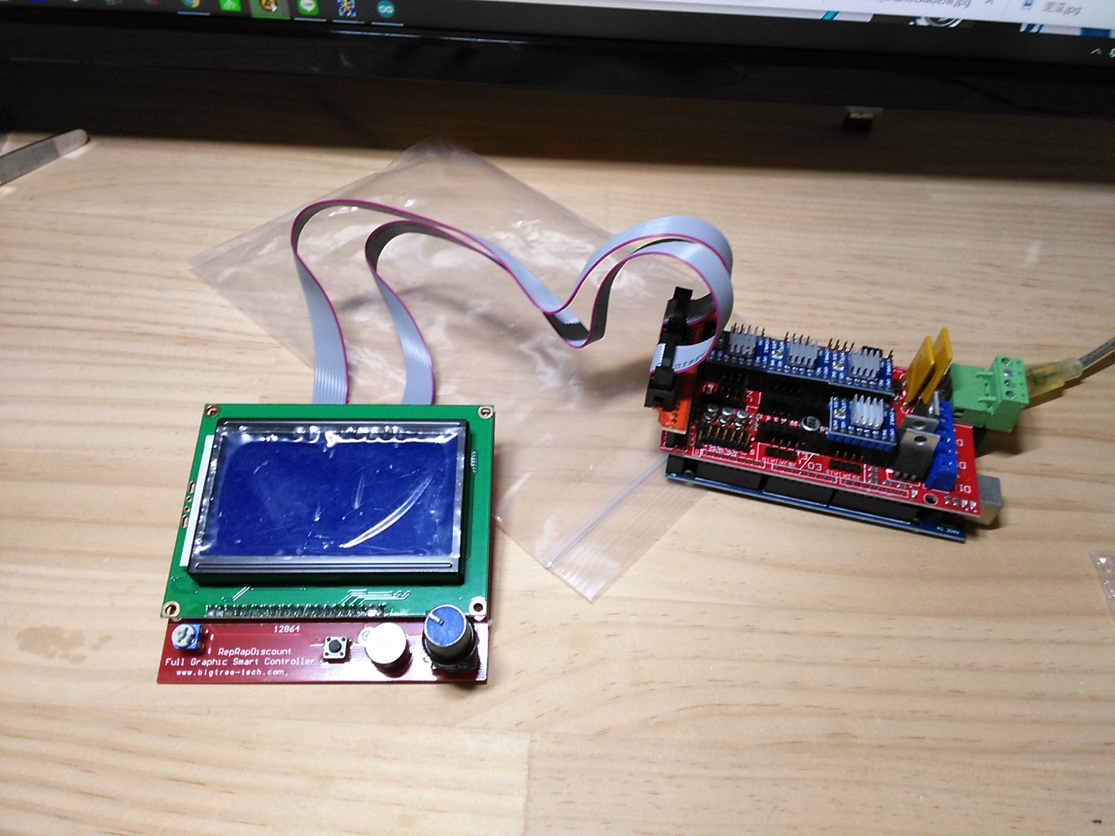
こちらはRAMPS基板に接続できるドットマトリクスディスプレイ。今回の目玉といえないこともない。
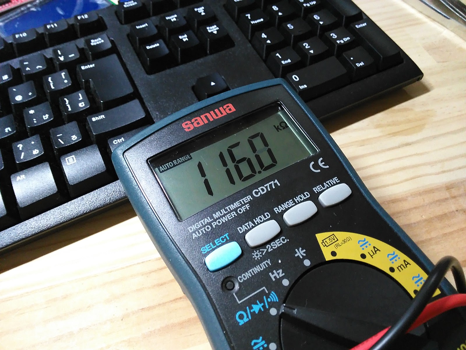
ではMarlinの設定に入りますが、その前に確認しておくことがあります。ホットエンドの温調に使用するサーミスタの定格です。これね。銀色の缶みたいなヒータのそば、白いハーネスの先端に見える小さな部品です。温度に応じて抵抗が変化するので、その値からヘッドの温度を知るのです。サーミスタの定格と設定が違っていると温度が合いませんし、危険であります。
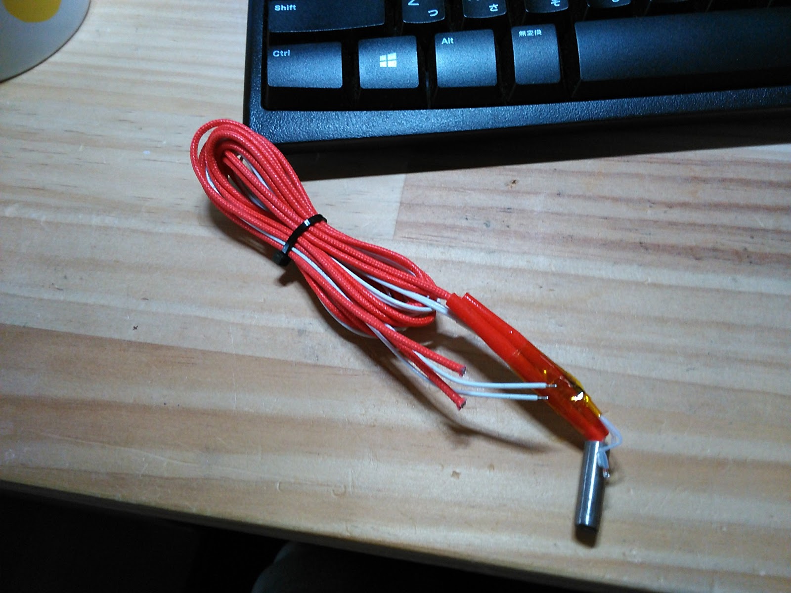
調べてみますと、室温で116kΩ。手で触ると100kΩを切るところまで下がります。
間違いなくいわゆる100kΩ品です。
では設定に入ります。
以下非常に長文になりますので【長文注意】をつけておきます。
設定は基本的にArduino IDE上でConfiguration.hファイルの中身をいじっていくことで行います。が、これが盛りだくさんなのです。ネットにはあちこちに情報が分散していますが、毎回調べるのも大変なので、私自身の備忘録の意味で全体を記録しておこうと思います。
Marlinファームウェアのファイル群、ドキュメント共にgithubにあります。今後も更新が進むと思いますが、本日のインストール時点での情報としてまとめておきます。
以下、documentsの_configuration内configuration.mdファイルと、Configuration.hのコメントを並行して参照しています。両者で記載の順番が違ってたりしますが、前後しているだけで項目自体はほぼあっています。
では行きます。訳は意訳でもないレベルの適当です。細かい突込みはご容赦願います。
青はdocumentsまたはコメント、黒は私のコメント。なんJ語になっているのは超意訳あるいは備忘コメント、赤は私が今回デフォルトから変更した設定値。
*******************************************
## Before You Begin
To get your core `Configuration.h` settings right you’ll need to know the following things about your printer:
コンフィグいじる前に以下のことは調べとけよ
– Printer style, such as Cartesian, Delta, CoreXY, or SCARA
→Cartesian。普通のXYZ方式ね。
– Driver board, such as RAMPS, RUMBA, Teensy, etc.
→RAMPS1.4
– Number of extruders
→ひとつ
– Steps-per-mm for XYZ axes and extruders (can be tuned later)
→これは動き出してから改めて設定する
– Endstop positions:リミットスイッチ
→全軸ともミニマム位置
– Thermistors and/or thermocouples
→サーミスタで100kΩのやつ
– Probes and probing settings:ホットエンドの位置を検出するセンサ
→ねえよ
– LCD controller brand and model
→RepRapDiscount Full Graphic Smart Controller
– Add-ons and custom components
→予定なし
#define SERIAL_PORT 0
“`
The index of the on-board serial port that will be used for primary host communication. Change this if, for example, you need to connect a wireless adapter to non-default port pins. Serial port 0 will be used by the Arduino bootloader regardless of this setting.
#define BAUDRATE 115200
シリアルのスピードがデフォでは250000になっているので、念のためよく見る115200に下げときます。
#define MOTHERBOARD BOARD_RAMPS_14_EFB
“`
The most important setting is Marlin is the motherboard. The firmware needs to know what board it will be running on so it can assign the right functions to all pins and take advantage of the full capabilities of the board. Setting this incorrectly will lead to unpredictable results.
Marlinさんは自分がどんなハードウェア上で動くのかわからんから教えてや
Using `boards.h` as a reference, replace `BOARD_RAMPS_14_EFB` with your board’s ID. The `boards.h` file has the most up-to-date listing of supported boards, so check it first if you don’t see yours listed here.
選べるハードは以下みたいにboards.hに書いてあるで
boards.h
#define BOARD_RAMPS_14_EFB 43 // RAMPS 1.4 (Power outputs: Hotend, Fan, Bed)
#define BOARD_RAMPS_14_EEB 44 // RAMPS 1.4 (Power outputs: Hotend0, Hotend1, Bed)
#define BOARD_RAMPS_14_EFF 45 // RAMPS 1.4 (Power outputs: Hotend, Fan0, Fan1)
#define BOARD_RAMPS_14_EEF 46 // RAMPS 1.4 (Power outputs: Hotend0, Hotend1, Fan)
#define BOARD_RAMPS_14_SF 48 // RAMPS 1.4 (Power outputs: Spindle, Controller Fan)
//#define CUSTOM_MACHINE_NAME “3D Printer”
“`
This is the name of your printer as displayed on the LCD and by `M115`. For example, if you set this to “My Delta” the LCD will display “My Delta ready” when the printer starts up.
このマシンに名前つけてええんやで
#define CUSTOM_MACHINE_NAME “Mirata_Designed”
//#define MACHINE_UUID “00000000-0000-0000-0000-000000000000”
“`
A unique ID for your 3D printer. A suitable unique ID can be generated randomly at [uuidgenerator.net](http://www.uuidgenerator.net/version4). Some host programs and slicers may use this identifier to differentiate between specific machines on your network.
このプリンタにIDつけてええで
IDつけとくとスライスするときに(お前が二台以上プリンタ持ってるなら)区別つけて作業ができるから便利やで
#define MACHINE_UUID “5053a184-b63e-41fe-8ba9-390c195a5c53”
上にあるURLでランダムなIDつけてくれます。
#define EXTRUDERS 1
“`
This value, from 1 to 4, defines how many extruders (or E steppers) the printer has. By default Marlin will assume separate nozzles all moving together on a single carriage. If you have a single nozzle, a switching extruder, a mixing extruder, or dual X carriages, specify that below.
This value should be set to the total number of E stepper motors on the machine, even if there’s only a single nozzle.
エクストルーダがいくつあるか教えてや
これはモータの数や、ノズルの数やないで
#define DEFAULT_NOMINAL_FILAMENT_DIA 3.00
“`
This is the “nominal” filament diameter as written on the filament spool (1.75, 2.85, 3.0). If you typically use 1.75mm filament, but physically measure the diameter as 1.70mm, you should still use 1.75 if that’s what you have set in your slicer.
フィラメントの太さをおしえてくれや、だいたいでええ
#define SINGLENOZZLE
“`
Enable `SINGLENOZZLE` if you have an E3D Cyclops or any other “multi-extruder” system that shares a single nozzle. In a single-nozzle setup, only one filament drive is engaged at a time, and each needs to retract before the next filament can be loaded and begin purging and extruding.
これはフィラメントの入り口がいくつかあって、出口が一つのヘッドを使っている奴のための設定や、お前には関係ない
### Switching Extruder
### Switching Nozzle
### Mixing Extruder
### Prusa MMU2 (Marlin 2.0)
### Hotend Offsets
#define POWER_SUPPLY 1
“`
Use this option to specify the type of power supply you’re using. Marlin uses this setting to decide how to switch the power supply on and off. The options are None (0), ATX (1), or X-Box 360 (2). For a non-switchable power supply use 0. A common example of this is the power “brick” (like a big laptop power supply). For a PC power supply (ATX) or LED Constant-Voltage Power Supply select 1. These are the most commonly-used power supplies.
どんなでんげんつないでるんや、どうせ普通の定電圧電源やろ
なら気にせんでええ 0にしとけ
### Temperature Sensors
Temperature sensors are vital components in a 3D printer. Fast and accurate sensors ensure that the temperature will be well controlled, to keep plastic flowing smoothly and to prevent mishaps. Use these settings to specify the hotend and bed temperature sensors. Every 3D printer will have a hotend thermistor, and most will have a bed thermistor.
#define TEMP_SENSOR_0 1
#define TEMP_SENSOR_1 0
#define TEMP_SENSOR_2 0
#define TEMP_SENSOR_3 0
#define TEMP_SENSOR_4 0
#define TEMP_SENSOR_BED 0
#define TEMP_SENSOR_CHAMBER 0
ホットエンドのサーミスタ(SENSOR_0)はなんや
100kΩならデフォルトの1や
// Dummy thermistor constant temperature readings, for use with 998 and 999
//#define TEMP_SENSOR_1_AS_REDUNDANT
#define MAX_REDUNDANT_TEMP_SENSOR_DIFF 10
Enable this option to use sensor 1 as a redundant sensor for sensor 0. This is an advanced way to protect against temp sensor failure. If the temperature difference between sensors exceeds `MAX_REDUNDANT_TEMP_SENSOR_DIFF` Marlin will abort the print and disable the heater.
センサを二つ使って安全対策ができるで。おんなじところにつけとけば二つの値が違ったときはなんかおかしいということや。そん時は止めてやるで。
### Temperature Stability
Extruders must maintain a stable temperature for `TEMP_RESIDENCY_TIME` before `M109` will return success and start the print. Tune what “stable” means using `TEMP_HYSTERESIS` and `TEMP_WINDOW`.
ホットエンドがあったまったらプリントスタートや。あったまって安定したとみなす時間を設定するんやで。
### Temperature Ranges
These parameters help prevent the printer from overheating and catching fire. Temperature sensors report abnormally low values when they fail or become disconnected. Set these to the lowest value (in degrees C) that the machine is likely to experience. Indoor temperatures range from 10C-40C, but a value of 0 might be appropriate for an unheated workshop.
If any sensor goes below the minimum temperature set here, Marlin will **shut down the printer** with a “MINTEMP” error.
Maximum temperature for each temperature sensor. If Marlin reads a temperature above these values, it will immediately shut down for safety reasons. For the E3D V6 hotend, many use 285 as a maximum value.
ホットエンドがこれ以下の温度やったらなんかおかしいと考えるんや。サーミスタが外れたり、ヒータが切れたりした時の対策や。
### PID
Marlin uses PID (Proportional, Integral, Derivative) control ([Wikipedia](https://en.wikipedia.org/wiki/PID_controller)) to stabilize the dynamic heating system for the hotends and bed. When PID values are set correctly, heaters reach their target temperatures faster, maintain temperature better, and experience less wear over time.
Most vitally, correct PID settings will prevent excessive overshoot, which is a safety hazard. During PID calibration, use the highest target temperature you intend to use (where overshoots are more critical).
おれはPID制御ができるんやで。でもちゃんと設定せんとお前が思った通りにはならんのやで。
#### Hotend PID Options
Disable `PIDTEMP` to run extruders in bang-bang mode. Bang-bang is a pure binary mode – the heater is either fully-on or fully-off for a long period. PID control uses higher frequency PWM and (in most cases) is superior for maintaining a stable temperature.
#define PIDTEMP
PIDをつかわんのならここをコメントアウトするんや。そうするとバンバンモードになるんやで。
PID制御とバンバンモードの違いは現在温度が目標温度から外れているときの加熱挙動の違いです。
PID制御は微妙に、バンバンモードは雑に加熱のON/OFFをします。
イメージ的には、いやものすごくイメージで説明しますと、小学校の掃除の時間に箒を手のひらに立ててバランスをとって遊んだことがあると思いますが、あの時の箒が直立している状態が温度が目標値にある状態、そしてそれを維持しようとする微妙な手の動きがPID制御に近いです。それに対してバンバン制御は机の上に箒を立てるイメージです。倒れそうになったら元に戻して手を放す。それの繰り返し。
Enable `PID_AUTOTUNE_MENU` to add an option on the LCD to run an Autotune cycle and automatically apply the result. Enable `PID_PARAMS_PER_HOTEND` if you have more than one extruder and they are different models.
PID制御の設定は難しいんやで。だからそれを自動でやれるモードも作ってやったんや。
でもな、これは種類が違うエクストルーダが二個以上ついてる時だけや。お前には関係ない。
Sample PID values are included for reference, but they won’t apply to most setups. The PID values you get from `M303` may be very different, but will be better for your specific machine.
// Ultimaker
#define DEFAULT_Kp 22.2
#define DEFAULT_Ki 1.08
#define DEFAULT_Kd 114
PIDを設定するにはこの3つの値を適切にきめんとあかん。例を挙げてやるが、お前のマシンでちゃんと設定せんと多分ダメや
#### Bed PID Options
お前には関係ない
### Safety
#### Prevent Cold Extrusion
So-called “cold extrusion” can damage a machine in several ways, but it usually just results in gouged filament and a jammed extruder. With this option, the extruder motor won’t move if the hotend is below the specified temperature. Override this setting with `M302` if needed.
#define PREVENT_COLD_EXTRUSION
#define EXTRUDE_MINTEMP 170
ホットエンドの温度がこれ以下の時は言われてもフィラメント動かさんで
#### Prevent Lengthy Extrude
A lengthy extrusion may not damage your machine, but it can be an awful waste of filament. This feature is meant to prevent a typo or glitch in a `G1` command from extruding some enormous amount of filament. For Bowden setups, the max length should be set greater than or equal to the load/eject length.
#define PREVENT_LENGTHY_EXTRUDE
#define EXTRUDE_MAXLENGTH 1000
フィラメントの使い過ぎを専用にこの長さを決めるんや。一回のプリントでこれ以上はフィラメント使わんのやで。
今回のプリンタは大型なので、この値は思いっきりでかくしています。1000mまでフィラメント送れます(笑
#### Thermal Protection
Thermal protection is one of the most vital safety features in Marlin, allowing the firmware to catch a bad situation and shut down heaters before it goes too far. Consider what happens when a thermistor comes loose during printing. The firmware sees a low temperature reading so it keeps the heat on. As long as the temperature reading is low, the hotend will continue to heat up indefinitely, leading to smoke, oozing, a ruined print, and possibly even fire.
Marlin offers two levels of thermal protection:
1. Check that the temperature is actually increasing when a heater is on. If the temperature fails to rise enough within a certain time period (by default, 2 degrees in 20 seconds), the machine will shut down with a “`Heating failed`” error. This will detect a disconnected, loose, or misconfigured thermistor, or a disconnected heater.
2. Monitor thermal stability. If the measured temperature drifts too far from the target temperature for too long, the machine will shut down with a “`Thermal runaway`” error. This error may indicate poor contact between thermistor and hot end, poor PID tuning, or a cold environment.
ヒータが過熱すると火事になるやろ、だからなんかおかしいと思ったら止めるようにしてるんやで。おかしいと思うポイントは二つや。一つ目はヒーターいれたらちゃんと温度が上がるかどうかを見ることや。入れたのに温度が上がらんかったらどう考えてもおかしいやろ。そして二つ目は温度が安定しているかどうかや。温度を一定に保つのにいっつもヒーターいれとかないかんとしたらそれもおかしいやろ。
## Kinematics
### CoreXY
### Delta
### SCARA
駆動の形式や。お前には関係ない。
## Endstops
In open loop systems, endstops are an inexpensive way to establish the actual position of the carriage on all axes. In the procedure known as “homing,” each axis is moved towards one end until the endstop switch is triggered, at which point the machine knows that the axis is at the endstop (home) position. From this point on, the machine “knows” its position by keeping track of how far the steppers have been moved. If the machine gets out of step for any reason, re-homing may be required.
リミットスイッチはだいじや。リミットスイッチがあってはじめてホームポジションが決まるんや。
### Endstop Plugs
Specify all the endstop connectors that are connected to any endstop or probe. Most printers will use all three min plugs. On delta machines, all the max plugs should be used. Probes can share the Z min plug, or can use one or more of the extra connectors. Don’t enable plugs used for non-endstop and non-probe purposes here.
#define USE_XMIN_PLUG
#define USE_YMIN_PLUG
#define USE_ZMIN_PLUG
//#define USE_XMAX_PLUG
//#define USE_YMAX_PLUG
//#define USE_ZMAX_PLUG
リミットスイッチがどんなふうについてるのかを決めるんやで。デフォルトはXYZ全部ミニマム側や。デルタ型はMAX側にするから気つけや。
#define ENDSTOPPULLUPS
By default all endstops have pullup resistors enabled. This is best for NC switches, preventing the values from “floating.” If only some endstops should have pullup resistors, you can disable `ENDSTOPPULLUPS` and enable pullups individually.
普通は制御側のハードでプルアップしてるはずや。お前があえて外にプルアップの回路をつなぐならここを設定するんやで。
### Endstop Inverting
// Mechanical endstop with COM to ground and NC to Signal uses “false” here (most common setup).
普通はプルアップがグランドに落ちたらスイッチが押されたということや。違うならここを反対にするんや。
### Endstop Interrupts
Enable this feature if all enabled endstop pins are interrupt-capable.
This will remove the need to poll the interrupt pins, saving many CPU cycles.
お前のリミットスイッチが全部割り込みポートにつながってるならここのコメントアウトを外すんやで。そうすればいちいちスイッチ見に行かんでええから楽や。
## Movement
* Stepper Drivers
*
* These settings allow Marlin to tune stepper driver timing and enable advanced options for
* stepper drivers that support them. You may also override timing options in Configuration_adv.h.
*
* A4988 is assumed for unspecified drivers.
何のモータドライバチップ使ってるんや。A4988やったらデフォルトやからなんもせんでええ。
* Endstop Noise Filter
*
* Enable this option if endstops falsely trigger due to noise.
* NOTE: Enabling this feature means adds an error of +/-0.2mm, so homing
* will end up at a slightly different position on each G28. This will also
* reduce accuracy of some bed probes.
* For mechanical switches, the better approach to reduce noise is to install
* a 100 nanofarads ceramic capacitor in parallel with the switch, making it
* essentially noise-proof without sacrificing accuracy.
* This option also increases MCU load when endstops or the probe are enabled.
* So this is not recommended. USE AT YOUR OWN RISK.
* (This feature is not required for common micro-switches mounted on PCBs
* based on the Makerbot design, since they already include the 100nF capacitor.)
*/
//#define ENDSTOP_NOISE_FILTER
リミットスイッチがノイズで誤動作する心配があるならここで設定するんやで。普通はCRの時定数が乗ってるからなんもせんで大丈夫のはずや。
### Distinct E Factors
Enable `DISTINCT_E_FACTORS` if your extruders are not all mechanically identical. With this setting you can optionally specify different steps-per-mm, max feedrate, and max acceleration for each extruder.
エクストルーダが二つ以上あるやつの設定や。お前には関係ない。
違うのがついてる奴は別々に設定せんといかんやろ、そのあたりをやるとこや。
### Default Steps per mm
These are the most crucial settings for your printer, as they determine how accurately the steppers will position the axes. Here we’re telling the firmware how many individual steps produce a single millimeter (or degree on SCARA) of movement. These depend on various factors, including belt pitch, number of teeth on the pulley, thread pitch on leadscrews, micro-stepping settings, and extruder style.
#define DEFAULT_AXIS_STEPS_PER_UNIT { 80, 80, 4000, 500 }
ここはだいじや。なんパルスでどんだけモータが回るかを決めるところや。
これが間違ってると1mm動かすはずが5mm動いたりするんやで。
#### Default Max Feed Rate
In any move, the velocities (in mm/sec) in the X, Y, Z, and E directions will be limited to the corresponding `DEFAULT_MAX_FEEDRATE`.
#define DEFAULT_MAX_FEEDRATE { 300, 300, 5, 25 }
軸を動かす速さはいろんな条件でかわるんやが、何がどうなってもここの設定以上のスピードにはならんのやで。脱調せんレベルに抑えとくべきや。
### Acceleration
#### Default Max Acceleration
When the velocity of any axis changes, its acceleration (or deceleration) in mm/s/s is limited by the current max acceleration setting. Also see the *jerk* settings below, which specify the largest instant speed change that can occur between segments.
A value of 3000 means that an axis may accelerate from 0 to 3000mm/m (50mm/s) within a one second movement.
軸を動かすときにどんくらいで加速するかの設定や。
これ以上の加速はせんのやで。
Jerk sets the floor for accelerated moves. If the change in top speed for a given axis between segments is less than the jerk value for the axis, an instantaneous change in speed may be allowed. Limits placed on other axes also apply. Basically, lower jerk values result in more accelerated moves, which may be near-instantaneous in some cases, depending on the final acceleration determined by the planner.
Jerkちゅうのは急に動かすということや。加速はスライサーの計算によっていろいろ変わるんや。場合によっては加速無限大でいきなり低速で動くようなことにもなりかねん。
それを避けるためにはこの値をちゃんと設定するんやで。値が大きいほど急には動かんようになるで。
## Z Probe Options
### Probe Pins
Use this option in all cases when the probe is connected to the Z MIN endstop plug. This option is used for `DELTA` robots, which always home to MAX, and may be used in other setups.
You can use this option to configure a machine with no Z endstops. In that case the probe will be used to home Z and you will need to enable `Z_SAFE_HOMING` to ensure that the probe is positioned over the bed when homing the Z axis – done after X and Y.
#define Z_MIN_PROBE_USES_Z_MIN_ENDSTOP_PIN
プリント開始時のZ軸の高さを決めるためにプローブを使うことができるんや。でもプローブ持ってへんやつはリミットスイッチを代わりに使ってもええんやで
### Probe Type
Even if you have no bed probe you can still use any of the core `AUTO_BED_LEVELING_*` options below by selecting this option. With `PROBE_MANUALLY` the `G29` command only moves the nozzle to the next probe point where it pauses. You adjust the Z height with a piece of paper or feeler gauge, then send `G29` again to continue to the next point. You can also enable `LCD_BED_LEVELING` to add a “Level Bed” Menu item to the LCD for a fully interactive leveling process.
* The “Manual Probe” provides a means to do “Auto” Bed Leveling without a probe.
* Use G29 repeatedly, adjusting the Z height at each point with movement commands
* or (with LCD_BED_LEVELING) the LCD controller.
*/
//#define PROBE_MANUALLY
//#define MANUAL_PROBE_START_Z 0.2
プローブ持ってへんやつは手動で高さを決めてもええんやで。
液晶画面からメニューを選んで設定するんや。
でもそうしたかったらここのコメントを外すんやで。
#### Fix Mounted Probe
#### BLTouch
#### Servo Z Probe
#### Solenoid Probe
#### Z Probe Sled
#### Allen Key
### Probe Offsets
### Probing Speed
### Probe Double Touch
### Probe Clearance
### Probe Testing
このへんはお前には関係ない。だってお前プローブ持ってないやろ。
## Stepper Drivers
### Motor Enable
These options set the pin states used for stepper enable. The most common setting is 0 (`LOW`) for Active Low. For Active High use 1 or `HIGH`.
モータをイネーブルにする設定や。普通は0のままでええ。
### Motor Disable
Use these options to disable steppers when not being issued a movement. This was implemented as a hack to run steppers at higher-than-normal current in an effort to produce more torque at the cost of increased heat for drivers and steppers.
Disabling the steppers between moves gives the motors and drivers a chance to cool off. It sounds good in theory, but in practice it has drawbacks. Disabled steppers can’t hold the carriage stable. This results in poor accuracy and carries a strong probability of axial drift (i.e., lost steps).
Most 3D printers use an “open loop” control system, meaning the software can’t ascertain the actual carriage position at a given time. It simply sends commands and assumes they have been obeyed. In practice with a well-calibrated machine this is not an issue and using open loop is a major cost saving with excellent quality.
We don’t recommend this hack. There are much better ways to address the problem of stepper/driver overheating. Some examples: stepper/driver heatsink, active cooling, dual motors on the axis, reduce microstepping, check belt for over tension, check components for smooth motion, etc.
モータをDisableにするかどうかを決めるところや。でもな、基本的には触るな。
モータをDisableにするということは励磁を切るということや。オープンループの制御系で励磁を切るとモータが勝手に空回りしてもわからん。そん時はもうずれたままでプリントや。まずいやろ。やめとき。
### Motor Direction
These settings reverse the motor direction for each axis. Be careful when first setting these. Axes moving the wrong direction can cause damage. Get these right without belts attached first, if possible. Before testing, move the carriage and bed to the middle. Test each axis for proper movemnt using the host or LCD “Move Axis” menu. If an axis is inverted, either flip the plug around or change its invert setting.
モータが回る方向を決めるところや。おもてたのと違う方向に回るようならここを設定するんや。
### Toshiba Drivers
東芝のドライバ用や。お前には関係ない。
## Homing and Bounds
### Z Homing Height
This value raises Z to the specified height above the bed before homing X or Y. This is useful to prevent the head crashing into bed mountings such as screws, bulldog clips, etc. This also works with auto bed leveling enabled and will be triggered only when the Z axis height is less than the defined value, otherwise the Z axis will not move.
原点復帰するときにZ軸をどんくらいもちあげるかの設定や。
そのまま横に動かしたらいろいろ当たるかもしれんやろ。
### Homing Direction
Homing direction for each axis: -1 = min, 1 = max. Most cartesian and core machines have three min endstops. Deltas have three max endstops. For other configurations set these values appropriately.
原点復帰をするときの方向をどっちにするかのせっていや。
普通のXY方式やったら0側にあるやずやろ。自分のプリンタの形式に合わせて適当にせっていするんや。
### Software Endstops
Set to `true` to enable the option to constrain movement to the physical boundaries of the machine (as set by `[XYZ]_(MIN|MAX)_POS`). For example, `G1 Z-100` can be min constrained to `G1 Z0`. It is recommended to enable these options as a safety feature. If software endstops need to be disabled, use `M211 S0`.
ソフトでリミット位置を決める設定や。ハードスイッチで原点出さんと意味無いで。
普通はONにしとけ。
### Movement Bounds
With Marlin 1.1.5 and up you can directly specify the bed size. This allows Marlin to do extra logic related to the bed size when it differs from the movement limits below. If the XY carriage is able to move outside of the bed, you can specify a wider range below.
#define X_BED_SIZE 300
#define Y_BED_SIZE 250
ベッドのサイズをソフト的に設定するところや。
なんかの事情で実際のサイズと変えたいときはここをいじるんやで。
These values specify the physical limits of the machine. Usually the `[XYZ]_MIN_POS` values are set to 0, because endstops are positioned at the bed limits. `[XYZ]_MAX_POS` should be set to the farthest reachable point. By default, these are used as your homing positions as well. However, the `MANUAL_[XYZ]_HOME_POS` options can be used to override these, if needed.
#define X_MIN_POS 0
#define Y_MIN_POS 0
#define Z_MIN_POS 0
#define X_MAX_POS X_BED_SIZE
#define Y_MAX_POS Y_BED_SIZE
#define Z_MAX_POS 350
軸を動かせる最大距離を設定するのがここや。
## Filament Runout Sensor
フィラメント切れセンサの設定や。お前には関係ない。
## Bed Leveling
There are many cases where it’s useful to measure variances in bed height. Even if the bed on a 3D printer is perfectly flat and level, there may still be imperfections in the mechanics. For example, a machine may have a very flat bed, but a corner of the XY gantry is a half-mm high. The ends of the Z axis may not be perfectly level. The bed may move slightly in the Z plane as it moves in the X and/or Y plane. On a Delta there may be a lingering bowl-shape to its XY trajectory.
ベッドが平らじゃない奴はここでハイトマップを作れば幸せになれるで。
Bed Compensation or “— Bed Leveling” allows the machine -with a bed probe or user assistance- to take accurate measurements of the “bed height” at various points in the XY plane. With this data the machine can then adjust movement to align better to the tilt or “height” variances in the bed. (I’m scare-quoting “height” here because variances may come from other than the bed.)
### Debug Leveling
#### G26 Mesh Validation Pattern
### Leveling Fade Height
### Bed Leveling Style
### Linear / Bilinear Options
### Bilinear Options
### 3-Point Options
### Unified Bed Leveling Options
#### Probe Points
### Mesh Bed Leveling Options
ハイトマップを作るにはいろんなやり方があるんや。
好きなのを選べ。お前には関係無いがな。
### LCD Bed Leveling
`LCD_BED_LEVELING` adds a “Level Bed” menu to the LCD that starts a step-by-step guided leveling procedure that requires no probe. For Mesh Bed Leveling see [`G29` for MBL](/docs/gcode/G029-mbl.html), and for `PROBE_MANUALLY` see [`G29` for ABL](http://marlinfw.org/docs/gcode/G029-abl.html).
### Z Probe End Script
## Homing Options
### Bed Center at 0,0
### Manual Home Position
### Z Safe Homing
### Homing Speed
LCD表示器をつけてる奴はLCD表示に従って対話方式でハイトマップ作れるで。
やっぱりお前には関係無いがな。
/**
* Bed Skew Compensation
*
* This feature corrects for misalignment in the XYZ axes.
*
* Take the following steps to get the bed skew in the XY plane:
* 1. Print a test square (e.g., https://www.thingiverse.com/thing:2563185)
* 2. For XY_DIAG_AC measure the diagonal A to C
* 3. For XY_DIAG_BD measure the diagonal B to D
* 4. For XY_SIDE_AD measure the edge A to D
*
* Marlin automatically computes skew factors from these measurements.
* Skew factors may also be computed and set manually:
*
* – Compute AB : SQRT(2*AC*AC+2*BD*BD-4*AD*AD)/2
* – XY_SKEW_FACTOR : TAN(PI/2-ACOS((AC*AC-AB*AB-AD*AD)/(2*AB*AD)))
*
* If desired, follow the same procedure for XZ and YZ.
* Use these diagrams for reference:
*
* Y Z Z
* ^ B——-C ^ B——-C ^ B——-C
* | / / | / / | / /
* | / / | / / | / /
* | A——-D | A——-D | A——-D
* +————–>X +————–>X +————–>Y
* XY_SKEW_FACTOR XZ_SKEW_FACTOR YZ_SKEW_FACTOR
*/
当たり前だが、X軸とY軸は直交している必要があるやろ。
それが曲がってる奴はここで設定するとええ。
正方形書かせてみ。それが平行四辺形になってしまうやつは軸が直交してないということや。
## Extras 1
### EEPROM
#### EEPROM Options
### Host Keepalive
### Free Memory Watcher
### Inch Units
### Temperature Units
### LCD Material Presets
### Nozzle Park
### Nozzle Clean
### Print Job Timer
### Print Counter
お前には関係ない。
## LCD Language
### User Interface Language
Choose your preferred language for the LCD controller here. Supported languages include:
Code|Language||Code|Language||Code|Language
—-|——–||—-|——–||—-|——–
en|English (Default)||an|Aragonese||bg|Bulgarian
ca|Catalan||cn|Chinese||cz|Czech
de|German||el|Greek||el-gr|Greek (Greece)
es|Spanish||eu|Basque-Euskera||fi|Finnish
fr|French||gl|Galician||hr|Croatian
it|Italian||kana|Japanese||kana_utf8|Japanese (UTF8)
nl|Dutch||pl|Polish||pt|Portuguese
pt-br|Portuguese (Brazilian)||pt-|Portuguese (Brazilian UTF8)||pt_utf8|Portuguese (UTF8)
ru|Russian||sk_utf8|Slovak (UTF8)||tr|Turkish
uk|Ukrainian||||||
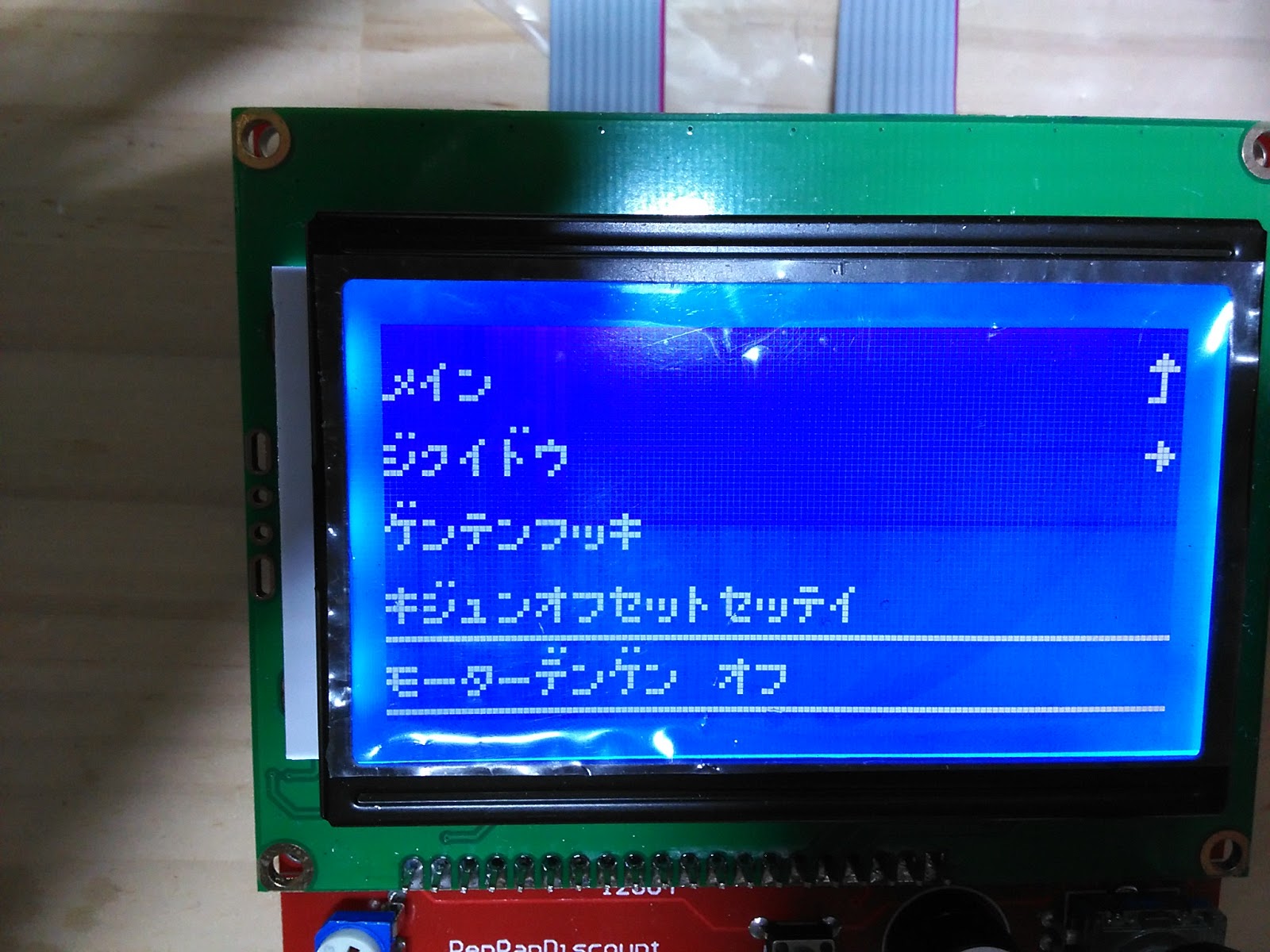
#define LCD_LANGUAGE kana_utf8
LCD表示を設定するところや。
日本語にしてもカタカナしか表示できんで。
### HD44780 Character Set
## LCD Type
The base LCD Type is either character-based or graphical. Marlin will automatically set the correct one for your specific display, specified below. Unless your display is unsupported by Marlin, you can leave these options disabled.
LCDがキャラクタタイプかグラフィカルな奴かを設定するところやけど、普通は自動で検出するからここはなんもせんでええ。
## SD Card
The `SDSUPPORT` option must be enabled or SD printing will not be supported. It is no longer enabled automatically for LCD controllers with built-in SDCard slot.
#define SDSUPPORT
SDカード使ってプリントしたい奴はここのコメントを外すんや。
さもないとSDカード使えんで。
ここは自動ではONにならんから気を付けるところや。
### SPI Speed
Uncomment ONE of these options to use a slower SPI transfer speed. This is usually required if you’re getting volume init errors.
//#define SPI_SPEED SPI_HALF_SPEED
//#define SPI_SPEED SPI_QUARTER_SPEED
//#define SPI_SPEED SPI_EIGHTH_SPEED
SPI通信の速度を設定するところや。
お前には関係ない。
### Enable CRC
## Encoder
### Encoder Resolution
### Encoder Direction
## Speaker
By default Marlin assumes you have a buzzer with a fixed frequency. If you have a speaker that can produce tones, enable it here.
データ転送でCRC確認するかとか、エンコーダとかスピーカーとかの設定や。
お前には関係ない。
## LCD Controller
Marlin includes support for several controllers. The two most popular controllers supported by Marlin are:
– `REPRAP_DISCOUNT_SMART_CONTROLLER` A 20 x 4 character-based LCD controller with click-wheel.
– `REPRAP_DISCOUNT_FULL_GRAPHIC_SMART_CONTROLLER` A monochrome 128 x 64 pixel-based LCD controller with click-wheel. Able to display simple bitmap graphics and up to 5 lines of text.
Most other LCD controllers are variants of these. Enable just one of the following options for your specific controller:
#define REPRAP_DISCOUNT_SMART_CONTROLLER
### Character LCDs
### Graphical LCDs
// RepRapDiscount FULL GRAPHIC Smart Controller
// http://reprap.org/wiki/RepRapDiscount_Full_Graphic_Smart_Controller
//
#define REPRAP_DISCOUNT_FULL_GRAPHIC_SMART_CONTROLLER
お前が使うLCDがどこの何かを設定するところや。
### Keypads
## Extras 2
### Fan PWM
### Temperature Status LEDs
### Photo Pin
### SkeinForge Arc Fix
## Extras 3
### Paste Extruder
Marlin includes support for the [Baricuda Extruder for 3D Printing Sugar and Chocolate](http://www.thingiverse.com/thing:26343) also [hosted on GitHub](http://www.github.com/jmil/BariCUDA). The feature adds the codes `M126`, `M127`, `M128`, and `M129` for controlling the pump and valve of the Baricuda.
こまごまとした話や
お前には関係ない。
### RGB Color LEDs
#### Printer Event LEDs
### Servos
#### Number of Servos
#### Servo Deactivation
*******************************************
長い!
一通り編集したら書き込んで動作を確認します。
何やら動いている様子。
ヒータとかサーミスタとか繋いでないので、表示がおかしいですが。
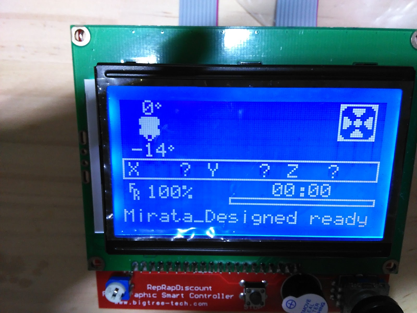
日本語表示はこんな感じ。
英語のほうが見やすいかな。
ということで、とりあえずMarlinも動く様子。
おそらく回転方向とか、速度とか、パルスレートとか違っていると思いますが、ここまでで接続してみて動かしましょう。